Monocular Camera Calibration
We will be using Zhang’s Method for camera calibration which uses known planar objects for estimating camera parameters (fx, fy, cx, cy) and distortion coefficients (Default 5 parameters – k1, k2, p1, p2, k3: kx is for radial distortion and px is for tangential distortion). We will be using OpenCV so that we could use pre-built library functions. You can follow along using the provided GitHub repository in the Code Reference section at the end.
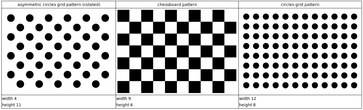
Fig: Commonly Used Calibration Patterns – Source: 3DiVi Docs
Calibration Patterns
Warning
Make sure the pattern is completely flat. If you are using glue to paste the pattern on a flat object, make sure there is no any bubbles after pasting.
1. Chessboard
Parameters:
width: total number of inner corners in X-axis
height: total number of inner corners in Y-axis
Attention
For chessboard pattern, it is recommended to choose odd and even combination for height and width so that orientation detection is robust. Visually, you can verify that by finding 2 black and 2 white squares as the corners of the whole pattern.
Recommended size: (9, 6)
2. Symmetric Circles
Parameters:
width: total number of circular blobs in X-axis
height: total number of circular blobs in Y-axis
Attention
For symmetric circles, it is recommended to choose odd and odd combination for height and width so that center circle identification becomes easier.
Recommended size: (7, 7)
3. Asymmetric Circles
It if often recommended pattern because of its orientation robustness due to asymmetricity.
Parameters (columns x rows):
columns: total number of columns in each row
rows: total number of hoirzontal rows
Attention
For asymmetric circles, no restrictions but recommended even and odd pattern.
Recommended size: (4, 11)
Data Preparation
Click about 10-20 images of the pattern in different orientations making sure images do not have same viewpoint. Also, make sure to have whole pattern in the image without any clipping at the edges.
Tip
Rename the clicked images like img_00, img_01, … in a sequence and store in a directory. Since, it would be easier to remove bad images later on which give high error.
Calibration Steps
Define pattern size and required parameter values of printed pattern.
import cv2
import numpy as np

CHECKERBOARD_DIM = (7,10)
CHECKERBOARD_SQUARE_SIZE = 20 ## In mm
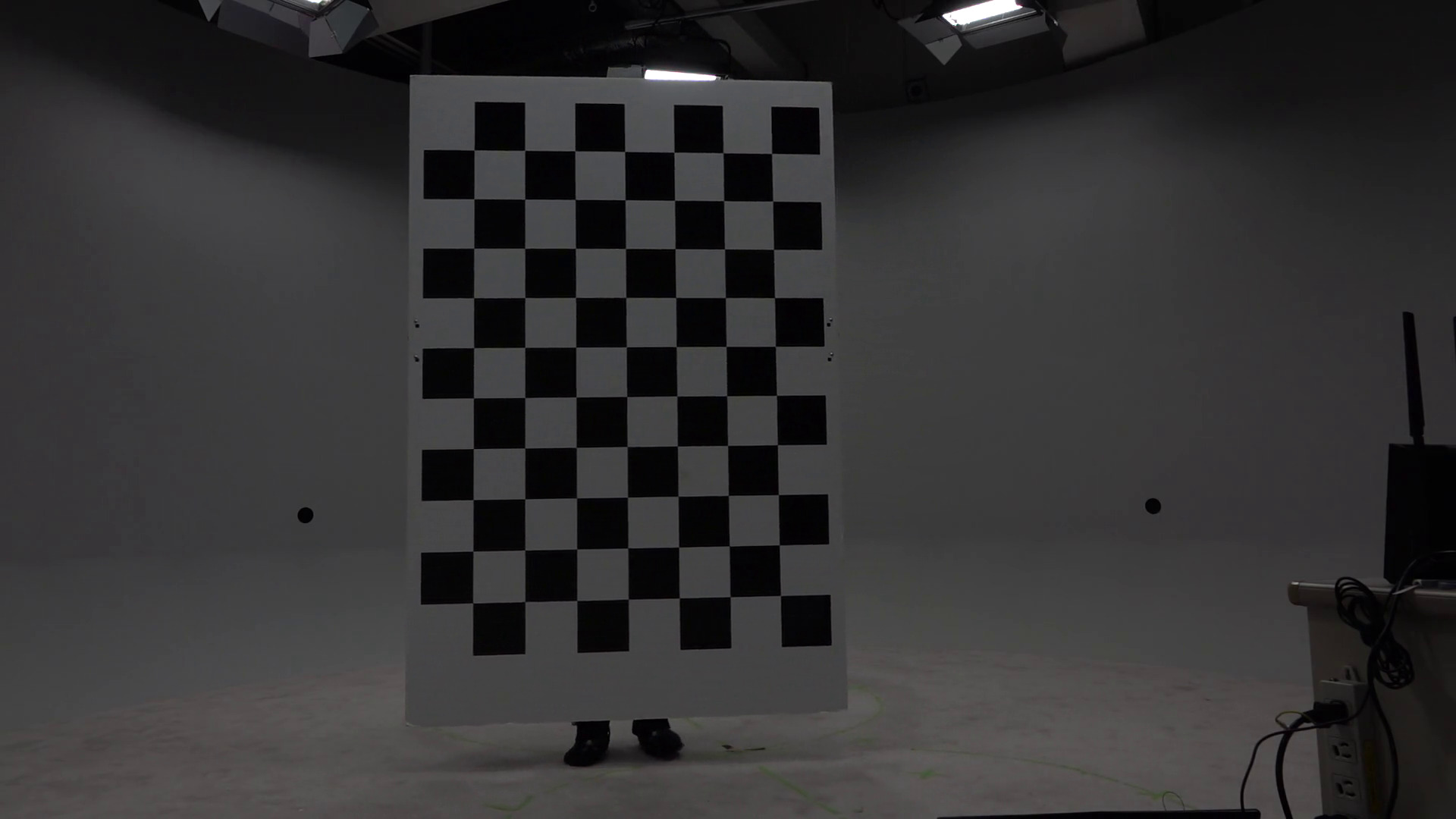
Fig: Chessboard pattern being used
2. Create two lists obj_points and img_points to store the real-world 3D coordinates and corresponding pixel coordinates respectively.
# Creating vector to store vectors of 3D points for each checkerboard image
objpoints = []
# Creating vector to store vectors of 2D points for each checkerboard image
imgpoints = []

## Defining the world coordinates for 3D points
## X: left->right, Y: top->bottom, Z: out-of-the plane (can be obtained by X x Y)

## Assuming one square as one unit
## (0,0,0), (1,0,0), ..., (6,0,0), (0,1,0), (1,1,0), ..., (6,1,0), ...
objp = np.zeros((1, CHECKERBOARD_DIM[0] * CHECKERBOARD_DIM[1], 3), np.float32)
objp[0,:,:2] = np.mgrid[0:CHECKERBOARD_DIM[0], 0:CHECKERBOARD_DIM[1]].T.reshape(-1, 2)
Populating img_points from the images.
## Criteria for subpixel accuracy like 1.2 px
criteria = (cv2.TERM_CRITERIA_EPS + cv2.TERM_CRITERIA_MAX_ITER, 30, 0.001)

for fname in images:
    img = cv2.imread(fname) #BGR format
    gray = cv2.cvtColor(img,cv2.COLOR_BGR2GRAY)
    # Find the chess board corners
    # If desired number of corners are found in the image then ret = true
    ret, corners = cv2.findChessboardCorners(gray, CHECKERBOARD_DIM, cv2.CALIB_CB_ADAPTIVE_THRESH + cv2.CALIB_CB_FAST_CHECK + cv2.CALIB_CB_NORMALIZE_IMAGE)

    """
    If desired number of corners are detected,
    we refine the pixel coordinates and display
    them on the images of checker board
    """
    if ret:
        objpoints.append(objp)
        # refining pixel coordinates for given 2d points.
        corners2 = cv2.cornerSubPix(gray, corners, (11,11),(-1,-1), criteria)

        imgpoints.append(corners2)

        # Draw and display the corners
        img = cv2.drawChessboardCorners(img, CHECKERBOARD_DIM, corners2, ret)
Calibrate the camera
"""
Performing camera calibration by
passing the value of known 3D points (objpoints)
and corresponding pixel coordinates (imgpoints)
"""
ret, mtx, dist, rvecs, tvecs = cv2.calibrateCamera(objpoints, imgpoints, gray.shape[::-1], None, None)

# tvecs obtained have units based on size of square i.e. 1 = 1 chess square
scaled_tvecs = [tvec * CHECKERBOARD_SQUARE_SIZE for tvec in tvecs]
Note
Camera matrix (mtx): Intrinsic parameters depend upon image size i.e. this camera matrix works for given image height and weight say h and w. If you use this for different height and width say h2 and w2 but with same aspect ratio, you can just scale i.e. \(f_{x\_new} = \frac{f_x * h_2}{h}\), … and so on. But, if aspect ratios are different, then calibrate with new images of same aspect ratio.
Distortion coefficients (dist): These are unaffected by image size or aspect ratio.
Rodrigues vectors (rvecs) and Translation vectors (tvecs): rvecs and tvecs are the poses of camera (6 DoF) with respect to individual images used for calibration unlike camera matrix (which is only one and same for all images). rvec is unaffected by using length of one chessboard square as unit length but tvec is affected, so tvec must be scaled. rvec is concise way to represent rotation with a 3D vector whose direction represents axis of rotation and magnitude represents the angle (in radians) by which coordinate frame will be rotated.
Optimize the camera matrix and get Region of Interest (ROI)
new camera mtx – Optimized intrinsic matrix designed to map the 3D coordinates to the 2D plane of the undistorted image
roi – largest inner rectangle within the undistorted image that contains ONLY valid (non-black) pixels.
ALPHA = 1 # Range: [0,1]
## If alpha=1, all pixels are retained with some extra black pixels
## If alpha=0, image with only valid pixels i.e. black borders are gone but some original edge pixels might be lost

newcameramtx, roi = cv2.getOptimalNewCameraMatrix(mtx, dist, (w,h), ALPHA, (w,h))

print("New camera matrix: \n")
print(newcameramtx)
print("Region of Interest: \n")
print(roi)
6. Observe reprojection errors and recalibrate in errors are high by removing the images that are producing large errors compared to others.
Reprojection error – Euclidean distance between detected pixel coordinate and projected pixel coordinate. Projected pixel coordinate obtained by forward projection i.e. multiplying by Projection matrix (i.e. Extrinsic and intrinsic parameters)
Attention
If good calibration, reprojection error < 0.1 px (best) or 0.2 px(tolerable).
See the individual and mean error, and remove the outlier images from calibration pipeline and recalibrate.
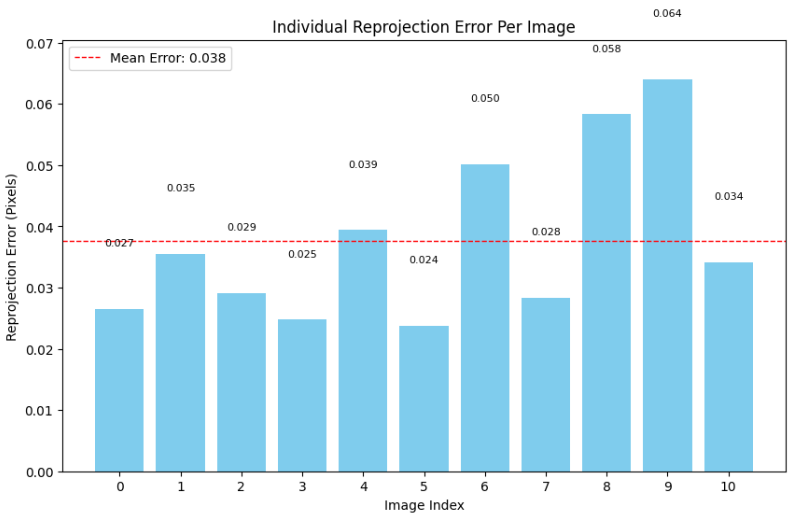
Fig: Reprojection Error of each image
In the shown example graph, it would be better if we remove img_08 and img_09 and recalibrate from the start.